


By Kevin Roberts
At the end of the last article, I left some of you with a bit of a cliffhanger. But it was a cliffhanger only for some of you because the rest of you clearly understood all the ramifications of the principle set forth in that article.
To repeat.
What happens if I disconnect the positive battery feed (assuming there is a single point to do so) and place a 194 bulb with a pigtail between the battery post and the battery cable terminal that I just removed, and then crank the engine?
If you got, really got, the gist of the previous article the answer is simple and two-fold:
- When you connect the 194 between the battery post and cable terminal, it lights up. (At least on a modern, read post 1950, fire truck).
- When you crank the engine, nothing else happens. The bulb simply stays illuminated. The current limiting function of the lowly 194 is preventing enough amperage from flowing to allow anything else to happen. (This is the same as if you had a circuit consisting of a bank of 4 batteries in parallel, 2/0 battery cables, and a 194 bulb as a load).
This is why the procedures delineated in this series are so important. You are training your brain to coordinate with the reality of the way electrons flow in a circuit. Once you do that, these types of questions lead to answers that are second nature. Or, to use the terminology in Daniel Kahneman’s excellent book “Thinking Fast and Slow”, you can use System Two (slow, deliberative, calculating thinking) to train System One (intuitive, subconscious, reactive thinking) to recognize what you are seeing. The key word that Kahneman uses for System One is that it is effortless. But as effortless as System One is, you might be surprised how much effort it takes System Two to train System One.
But if your System One answered the question posed at the end of the last article by thinking the bulb would blow when you cranked the engine, you simply must keep working on it. Training your brain is a difficult and time-consuming process if you do so intentionally. When I was young, I was the kid that took things apart and reassembled them to see how they worked. Often when I was done, they did not. Then I had an epiphany: my 8th grade science teacher explained the four-stroke cycle gasoline engine. I still remember the tingling feeling of my curiosity being both stimulated and satisfied. What I have determined to do throughout my training career is to allow my students to experience that and to give them the classes that I wish I had gotten in the years following 8th grade. (Mr. Bill Williams, if you’re out there, I would be thrilled to thank you in person)
So, is understanding how unbalanced loads function in a series circuit worthwhile? Yes, because it clears up the “black box” difficulty of knowing what but not knowing why or how. And in our field of emergency vehicle electrical, (not to mention automobiles in general) unbalanced loads in series are ubiquitous.
If we connect a very large load in series with a very small load, we already know that the small load will function normally, and the larger load will serve simply as a conductor. Can we use that principle to our advantage?
We have for many decades. We once had a 1939 Pontiac in the shop that had a starter engagement device on the floor. You used your foot to depress a button which connected on the other end to both the “Bendix” starter drive and the starter switch. Instead of using foot pressure, someone had the idea that an electric solenoid might work. The problem was that a human leg and foot has significant strength. To match that, the solenoid had to use a significant amount of amperage. In the good old days (which weren’t all that good) of 6-volt batteries, it was discovered that the solenoid amperage draw took too much battery oomph, and the engine would only crank properly under ideal conditions. Cold weather or a less than perfect battery meant the engine might crank too slow to start.
Then someone (I haven’t been able to determine who) got the idea that we could give the solenoid two windings. One would pull in the starter drive (often called the Bendix) to mesh with the flywheel and then make the electrical connection. The other winding would hold it in. All you had to do was disconnect the pull in winding after the “pulling in” was done and let the hold in winding, with its much lower amperage draw, maintain engagement. How do we disconnect the pull in winding at the precise time?
We invoke the principle of unbalanced loads in series.
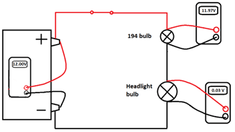
Remember this from last time?
Figure 1
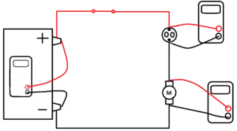
Let’s turn it into this.
Figure 2
Before we show numbers, let’s unpack the concept.
On the left we have the battery with a voltmeter that will show Source Voltage. Not OCV because we now have a closed circuit, so the battery is under load.
On the upper right we have a starter solenoid with the meter showing the Available Voltage to the starter solenoid primary circuit, the actuating coil.
At the lower right, we have the starter motor.
Yes, this is an incomplete diagram but that is necessary to make the point without distraction.
At the upper right we see the ignition solenoid primary circuit terminals (vertical). And we see the larger secondary circuit terminals (horizontal, with no conductors shown yet).
When the switch is turned to the crank position, it connects B+ to the solenoid. The B- half of this circuit is permanently routed through the starter motor main windings.
Why? Because the motor windings can conduct so much more amperage than the current limiting function of this pull-in coil allows. This means little practical effect on the motor. Just passing through.
A few reminders of the concept.
Remember that this is the primary circuit of the solenoid. (We’ll add the secondary circuit next time)
Remember the primary circuit must pull the starter drive into engagement with the flywheel and pull the solenoid switch into contact to energize the motor windings.
Remember that this is a pull in coil. Even though the load is miniscule compared to the starter, it is significant enough for us to want it disconnected during the cranking process and allow the much lower amperage hold in coil take over.
Remember finally that it must be disconnected at the precise time.
How would you design this circuit disconnect?
Next time, how the engineer did it.