


By Kevin Roberts
Last time we left you with this diagram.
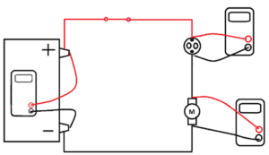
Figure 1
Our point was to introduce the practical application of unbalanced loads in a series circuit. You wouldn’t have thought it would take this many articles to do so. But the point of this article is not simply to explain the operation of a single component. It is to show how important thinking skills are to understanding vehicle electrical principles.
Remember that we are in series and any amperage flowing through the solenoid on the upper right means that is the same amperage flowing through the motor on the lower right (Kirchhoff’s Amperage Law). At least until the solenoid completes its travel. And yes, this travel time is measured in milliseconds, hence the meter readings as shown below could not actually be displayed. We just hit the “Pause Time” button to show this. Plus, the voltmeter reading on the starter motor is an over-estimate (in reality it is barely above zero).
See Figure 2 below.
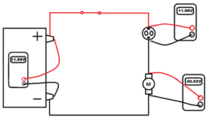
Figure 2
Remember that the only part of the solenoid circuit shown is the primary (coil) terminals, not the secondary high amperage flow through the solenoid contacts.
Remember that the solenoid draws so few amps compared to what the motor needs means the motor doesn’t turn. (If it had awareness, it might not even notice)
Remember that the initial amperage to draw in the solenoid with the starter drive is still significant (25-30 amps on an automobile, upwards of 50 amps on a medium duty diesel).
This means we need to disconnect this pull-in winding to allow those amps to help turn the starter.
Now let’s look at how we think about this. In this case, we need to avoid oversimplification when describing what a load is. The amperage that each load draws is unique. We have tiny loads, small loads, medium loads, large loads, and enormous loads. We have resistive loads, inductive loads, and capacitive loads. All of the above vary widely in amperage draw; not only from each other but each can vary itself over time. When I say that the pull in winding of the solenoid draws few amps, this is only in comparison to the starter motor, its ground path. But it draws enough amperage for us to want to take it out of the circuit during cranking. Thinking of all loads as unique is an essential habit that applies far beyond this circuit. It is necessary to recognize the similarity between a load, a resistance, a voltage drop, and a current limiter. But it is just as necessary to recognize the distinctions between the amount of load that each places on the circuit.
Back to our starter circuit. The ingenuity of this circuit is that the movement of the copper disc internal to the solenoid, not only connects the high amperage input to the high amperage output of the solenoid to operate the starter. It also effectively disconnects the pull-in winding from the circuit. Yes, you read that correctly.
Remember Available Voltage? Available Voltage is the voltage potential between the component’s (loads) positive and negative terminals. Normally, by opening the circuit, we eliminate that voltage potential. But in this case, there is a second way to eliminate the voltage potential (the Available Voltage) from the pull in coil. We can simply supply B+ to the ground side. I suspect you are skeptical about supplying B+ to the ground side of a nominal 12-volt DC load but think about this.
If we add the hold-in winding to the picture, we have this for the same few milliseconds. Figure 3 below.
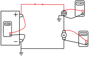
Figure 3
All we have added to the picture is the hold-in winding ground circuit. Notice that the B+ side of the hold-in circuit comes through the ignition switch the same as the pull-in winding. Let’s add some details, the heavy starter cables. See Figure 4 below.
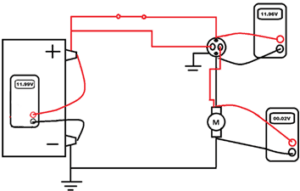
Figure 4
Here we see the way the starter cable is connected. Feel free to trace the circuit with a pen or pencil. The cable comes from the battery to the large input terminal on the solenoid. The other large terminal on the solenoid feeds the starter windings. Internal to the solenoid is that copper disc that is pulled in that connects the large B+ terminal to the large terminal that feeds the starter windings. The ingenuity is by supplying B+ to the starter windings, we see that same B+ show up on the cable that up until this moment was the ground to the pull-in solenoid. By converting that to B+ we both supply proper Available Voltage to the starter windings and remove ground potential from the pull-in coil winding.
So, the numbers you see on the meters above last a very short time. So short that you will not be able to read your meter fast enough to repeat this. Let’s look at a scope capture showing amperage (vertical) over time (horizontal). See Figure 5 below.
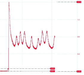
Figure 5
That little bump on the lower left of the pattern shows amperage draw when the key is turned to crank (vertical) and the duration in seconds of the pull-in coil amp draw (horizontal). In this case each grid section left to right equals one second. The duration of the pull-in coil amp draw is 33.42 milliseconds. This capture is from a case study developed for my Fire Apparatus Electrical class.
So, what happens after 33 milliseconds? The pull-in coil loses Available Voltage. As such, it stops drawing amperage and the hold-in coil takes over. The starter draws inrush amperage of around 1600 amps in Figure 5 above, and the meters now show how this affects our meter readings (for even less time than 33 milliseconds). As soon as the starter motor begins to turn, the inrush amps (also called locked rotor amps because it is the amperage draw before the rotor turns) begin to fall. Before they fall, we see the values shown in Figure 6 below.
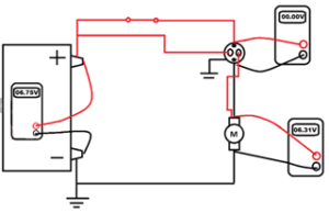
Figure 6
This looks pretty bad doesn’t it? And it is from a poorly functioning engine. But the meter readings you see only last for 26 milliseconds. As mentioned before, you could never actually see this on a meter. Once inrush settles down and the amperage stabilizes, you see something like this. See Figure 7 below.
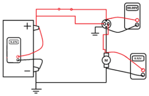
Figure 7
Still not great, but the last 2 figures show how by connecting the pull-in winding through the starter motor winding, we can remove Available Voltage from the pull-in winding by introducing Available Voltage to the starter motor.
To summarize: When you face something counterintuitive, like powering a very small load in series with a very large load, it may be a learning opportunity.
In this case we learned that you can eliminate Available Voltage to a component (turn it off) by changing the ground potential to system voltage. (In case you’re wondering if adding ground will still create a voltage spike, the answer is yes.)
This is a reminder that voltage is a potential energy level difference between two points in a circuit. Whether either (or neither) of the load terminals has potential positive voltage compared to ground is not important. Even the polarity can be unimportant. The only thing that matters is the Available Voltage to the load.
One final thought. Those of my readers that have used a scope to perform cranking amp testing: how many cylinders in the engine shown in the above capture? Provide reasons for your answer.